Background on Attitude and Orbit Control Systems (AOCS)
The information presented here is intended as background to understand
the aims and context of the AOCS Framework
Project. It describes a "typical" AOCS system with a bias towards ESA
scientific missions that tend to have the most complex kind of AOCS.
Satellite System Structure
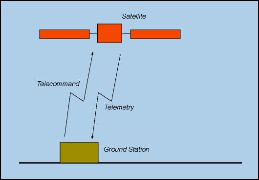 |
The figure at the side shows a "black box" view of a satellite
system. The satellite is controlled from a ground station through
a radiofrequency link. Depending on the mission, the link with the ground
station may be continuous or extend only over a section of the orbit. |
The satellite has two external interfaces:
-
Telecommands are commands sent by the
ground station to the satellite. They determine the behaviour of the satellite
and can sometimes override internal decisions taken by the on-board software.
Telecommands are normally sent as asynchronous data packets.
-
Telemetry data are sent by the satellite
to the ground. Telemetry data can be divided into two broad categories:
payload telemetry and housekeeping telemetry. The payload telemetry represents
the data collected by the satellite. In the case of an astronomical telescope,
for instance, the telemetry contains the pictures taken by the telescope.
Housekeeping telemetry gives information about the general status of the
satellite. Telemetry data are sent in packets. In the past, the sequence,
size and content of packets was fixed. In more recent systems, the ground
can select which packets to acquire and how often they should be provided.
 |
The figure at the side shows a typical internal architecture
of a satellite system. |
The satellite system is built around a system
bus (often called On Board Data Handling or OBDH bus in ESA missions).
The central on-board computer is the
bus master. The clients on the system bus are the satellite subsystems
and the payloads. Satellite subsystems have their own computer and may
even have an internal bus. In a common configuration, the AOCS constitutes
one separate satellite subsystem with a dedicated processor acting as a
client on the system bus. In an alternative configuration, the AOCS software
is hosted on the satellite central computer (perhaps as a dedicated process).
The data travelling over the system bus are telecommands and telemetry.
Telecommands are sent by the central computer to the subsystems and payloads,
while telemetry is sent by the subsystem and payload to the central computer.
Most normal communications between central computer and subsystems and
payloads take place over the system bus. Other links exist for use in special
situations such as initialization, power-up, failures or other non-nominal
tasks.
Back to Top, Back
to Aocs Framework Project Home
Satellite Operational Modes
A satellite can be in various operational modes. The operational mode determines
the behaviour of the satellite. Operational modes are adapted to mission
phases and to operational circumstances.
Typical operational modes include:
-
Stand-By Mode (SBM): in SBM, the satellite is inactive. It generates
basic housekeeping telemetry and listens for incoming telecommands but
takes no action to control the spacecraft. The satellite is typically in
this mode before it separates from the launcher and in the first seconds
after separation.
-
Initial Acquisition Mode (IAM): IAM is typically entered after the
satellite has separated from the launcher. In this mode the satellite must
perform its initialization and acquire a nominal attitude. IAM may also
be entered as part of the recovery sequence after a failure.
-
Normal Mode (NM): in NM the satellite performs the tasks for which
it was designed. Thus, for instance, an astronomical telescope in normal
mode performs scientific observations. Most of a mission is to be spent
in this mode
-
Safe Mode (SM): SM is entered after a very serious anomaly
has been detected. The objective of SM is to keep the satellite in a safe
state (ie. a state where no permanent damage is done to it or its instruments)
and to keep the radio link with the ground open (to allow the ground to
identify the cause of the anomaly and if possible to take remedial action).
Transitions from a mode to another may be either autonomous (ie. decided
by the on-board software without ground intervention) or may be commanded
by telecommands from the ground.
Back to Top, Back
to Aocs Framework Project Home
AOCS Subsystem Structure
The AOCS subsystem is one of the subsystems of a satellite. Its main function
is to control the attitude and the orbit of the satellite.
 |
The figure at the side shows an AOCS subsystem with its
external interfaces. The figure assumes an AOCS with a dedicated computer
separate from the central satellite computer. In an alternative configuration,
the AOCS is hosted on the central computer. |
The AOCS receives telecommands from the central
computer and it forwards telemetry data to it
over the system bus. It periodically acquires
measurements (on the satellite attitude and orbital position) from a set
of sensors and uses them to compute control signals
that are sent to a set of actuators. Other commands,
for special contingencies (such as for instance forcing the AOCS into safe
mode), may be routed over dedicated command lines.
 |
Because of its complexity, the AOCS is often organized around
a dedicated AOCS bus over which communications
between the AOCS computer and the AOCS sensors and actuators take place.
The resulting structure is shown in the figure at the side. |
Back to Top, Back
to Aocs Framework Project Home
AOCS Functions
The following main functions are typically carried out by an AOCS:
-
Attitude Control Function
At any given time, a nominal attitude is defined for the satellite.
This is the attitude that the satellite should ideally maintain. For instance,
in the case of a geostationary telecommunication satellite, the nominal
attitude has the satellite pointed towards the earth. In another example,
in the case of an astronomical observatory, the nominal attitude has the
boresight of the telescope pointed at the astronomical object that it is
desired to study.
The nominal attitude may be either telecommanded
by the ground or it may be generated internally by the AOCS software.
The attitude is controlled in closed loop and autonomously on-board
the satellite. The satellite attitude is controlled by applying torques
to the satellite. Torques are applied by attitude actuators.
The attitude control function is executed cyclically and its steps are:
-
Acquire data from attitude sensors;
-
Process sensor data to construct an estimate of the current satellite attitude;
-
Compute the deviation of the current attitude from the nominal attitude;
-
Compute a control torque to be applied to the satellite to bring the satellite
actual attitude closer to its nominal attitude;
-
Send commands to the attitude actuators to apply
the control torque to the satellite.
The typical frequency for the attitude control cycle is about 2
Hz but higher frequencies up to 20 Hz are possible.
-
Orbit Control Function
A nominal orbit is defined for the satellite. This is the orbit that
the satellite should maintain. The nominal orbit is defined by the ground.
The orbit of a satellite is controlled by applying forces to the satellite.
Forces are applied by delta-V actuators (so called because they
impart a velocity change, or delta-V, to the satellite).
Orbit control has traditionally been done in open loop mode under ground
control. This means that the ground:
-
determines the actual satellite orbit (by tracking the satellite as it
passes over the ground station);
-
computes the corrective forces that need to be applied to the satellite
to bring its actual orbit closer to the nominal orbit;
-
uplinks telecommands to the satellite commanding
the application of the corrective forces to the orbit actuators.
Recently, there has been a trend towards moving the orbit control
function to the satellite. In this case, an orbit control cycle would be
defined similar to the attitude control cycle. Its frequency would, however,
be much lower with typical periods ranging from several minutes to several
hours.
-
Telecommand
Processing
Telecommand packets are forwarded by the central satellite computer
to the AOCS subsystem. Telecommands arrive asynchronously.
The typical telecommand processing sequence is:
-
Perform consistency, validity, and other checks on the telecommand;
-
If the telecommand is accepted, execute it.
Typical commands that are sent to the AOCS through telecommands
include:
-
Set nominal attitude;
-
Command orbit control manoeuvre;
-
Power up/down an AOCS unit (sensor or actuator);
-
Command reconfiguration of AOCS units (fallback from prime to redundant
unit, see section 6.6);
-
Mark an AOCS unit as unhealthy (not to be used in future reconfigurations);
-
Command change of AOCS operational mode.
Some of the above commands override functions that can also be performed
autonomously by the AOCS.
-
Telemetry
Processing
The AOCS cyclically generates telemetry to be sent to the satellite
central computer. Depending on the system architecture, the forwarding
of telemetry packets to the central on-board computer may be initiated
by the AOCS itself or the packets may be autonomously acquired by the central
on-board computer.
Telemetry cycles have low frequencies of a fraction of an Hertz. The
format of the telemetry packets (ie, the type of information that they
contain) is determined by telecommands.
Typical data that are contained in a telemetry packet include:
-
power status of AOCS units;
-
health status of AOCS units;
-
current AOCS operational mode;
-
telecommand log (ID of received telecommands, execution status, etc.);
-
latest estimate of satellite attitude;
-
latest value of control torques computed by the AOCS;
-
latest readings from AOCS sensors;
-
latest set of commands sent to the AOCS actuators;
-
event log (log of special occurrences such as reconfigurations)
-
Failure Detection and Isolation
This is a cyclical function where the AOCS attempts to detect anomalies
and isolate their cause. This function is very mission specific and can
be very complex.
Typical checks that are performed in order to detect anomalies include:
-
Attitude Anomaly Detection (AAD):
verifies that the attitude is within a pre-specified permissible window.
The window may be defined with respect to the sun (eg. spacecraft X-axis
shall not deviate by more that 20 degrees from the sun line) or with respect
to the nominal attitude (eg. actual attitude shall not deviate from the
nominal attitude by more than 25 degrees). In both cases, a violation
of the attitude anomaly check indicates that the attitude control function
has failed. The size of the attitude window may be either fixed or settable
by telecommand. The attitude anomaly check is a failure detection only
method as it does not allow isolation of the cause of the anomaly.
-
Single Sensor Consistency Check: verifies that the output of a sensor
respects some physical constraints. Sensor outputs should for instance
lie within certain ranges, and variations across two consecutive readings
must be constrained to be below a certain threshold. The check thresholds
are generally settable by telecommand. This check allows both detection
and isolation of the failure.
-
Multi Sensor Consistency Check: sensors usually provide redundant
information (ie. several sensors may be measuring the same physical quantity,
for instance the sun direction). This check exploits the redundancy of
the measurements to detect and, if the degree of redundancy is sufficient,
isolate failures. The check thresholds are generally settable by telecommand.
-
Watchdog Alarm: the AOCS software cyclically generates a watchdog
event that is detected by dedicated hardware (the watchdog). If the
watchdog does not receive the event within a certain time-out, an anomaly
is assumed to have occurred. This mechanism only allows fault detection,
not fault isolation.
-
Failure Recovery
This is a cyclical function where the AOCS attempts to respond to the
detection of a failure by executing a failure recovery action.
Typical recovery actions that may be associated to detected failures
include:
-
AOCS software reset
-
notify the ground and take no further action
-
change operational mode (see below)
-
reconfigure a sensor or actutor where the failure is suspected to have
arisen
-
Reconfigurations
At any given instant in time, the AOCS is using only a subset of all
its available units. In most cases, there is a
redundancy requirement that dictates the presence of two sets of each units.
Hence, not more than half of all available equipment are ever used.
When the AOCS has detected a failure, it must attempt to recover by
performing a reconfiguration. A reconfiguration changes the set of units
that are being used by the AOCS at a certain instant in time. The intention
of a reconfiguration is to exclude the faulty unit. The configuration logic
is highly mission dependent. The following types of reconfigurations can
be identified:
-
Unit Reconfiguration: if the failure
detection and isolation function was able to isolate the faulty unit,
then the typical reconfiguration is a switch-over to the redundant copy
of the faulty unit. If, for instance, a consistency check on the output
of a sun sensor shows that the sensor is defective, then this function
will switch over to the redundant sun sensor. Overall system performance
should remain unaffected.
-
Subsystem Reconfiguration: if no fault isolation was possible, the
entire subsystem is reconfigured. This means that all units (including
the AOCS computer) are switched over to their redundant copies and the
subsystem is re-initialized. If, for instance, the attitude
anomaly safeguard has been violated, then it is known that a serious
fault has occurred but it is not possible to say which equipment is responsible
for it. In this case, all currently used hardware is switched off and there
is a switch over to the redundant sets.
-
Manoeuvre Execution
A manoeuvre is a sequence of actions that must be performed by the
AOCS at specified times to achieve a specified goal. Manoeuvres are normally
triggered by the ground by telecommands.
Examples of manoeuvres include:
-
A sequence of small torques imparted to the spacecraft to change its attitude
(in order, for instance, to change the direction of pointing of the spacecraft
payload).
-
A sequence of thruster firings to change the spacecraft orbit in open-loop
mode.
Back to Top, Back
to Aocs Framework Project Home
AOCS Operational Modes
The great variety of external conditions under which a satellite must operate
in a given mission, dictates the breakdown of the overall AOCS functionality
into several operational modes with each operational mode optimized for
certain mission conditions. The functionalities
of the AOCS are always the same but their implementation changes from
operational mode to operational mode. Consider for instance the attitude
control function. The accuracy with which the satellite attitude must be
aligned to the nominal attitude varies form mission phase to mission phase
(and hence from operational mode to operational mode). Consequently, different
control laws are used to implement this function depending on the required
accuracy.
An important difference between operational modes lies in the set of
AOCS
units the sensors and actuators that are used by the AOCS. In principle,
each operational mode has a different set of units that are the optimal
ones required to achieve the mode targets. Hence, a mode transition is
usually accompanied by a power-up and power-down sequence for some units.
 |
Mode architecture is very mission specific. The figure shows
a hypothetical mode sequence for a scientific satellite. The nomenclature
used for the various modes is explained below. Modes similar to those listed
in the figure will be found in most missions with slight differences of
functionality.
Mode transitions can either be commanded by the ground (or the central
on-board computer) through telecommands or they
can be decided autonomously by the AOCS software. In the latter case, however,
the ground retains the right to over-ride or inhibit AOCS-initiated transitions. |
-
Stand-By Mode (SBM): only the telecommand
and telemetry functions are active. The AOCS does
not perform any attitude or orbit control
functions and all the AOCS units, except the
AOCS computer, are switched off. This mode is typically used when the satellite
is still attached to the launcher or in the first seconds after separation
from the launcher.
-
Rate Reduction Mode (RRM): the objective is to reduce the angular
velocity of the satellite to a very small value . Thus, the attitude controller
in this mode is not concerned with the satellite attitude, but only with
the satellite angular rates. This mode is typically used after separation
from the launcher (launcher separation induces comparatively high angular
rates on the satellite).
-
Initial Attitude Acquisition (IAM): pre-condition for entry into
this mode is that the satellite angular rates are very low. This mode could
thus be entered after RRM. The satellite is slewed until it is oriented
according to a pre-defined attitude. This target attitude is often selected
in such a way as to have the solar array sun-pointing (to ensure a steady
power supply to the satellite) and the radiofrequency antennas earth-pointed
(to ensure a good telecommand and telemetry link).
-
Fine Pointing Mode (FPM): high accuracy mode where the satellite
attitude is finely controlled to reduce the attitude error (difference
between actual and nominal attitude) to the maximum possible extent. This
mode is typically used during scientific observations (scientific missions)
or earth observations (earth observation mission).
-
Slewing Mode (SLM): change the orientation of the satellite. This
is for instance required when a telescope must be pointed to a new target.
-
Orbit Control Mode (OCM): used when forces are imparted to the satellite
to change its orbit.
-
Safe Mode (SM): entered when a failure has
been detected and when no reconfiguration is possible to counter the failure.
This situation may arise for several reasons. For instance, a reconfiguration
may have been attempted and may have failed to restore nominal behaviour.
Alternatively, previous reconfigurations may have already caused a fall-back
to redundant units thus leaving the AOCS without further options for reconfigurations.
The objective of safe mode is to keep the satellite in a safe attitude
(ie. an attitude in which no permanent damage to the satellite or its instruments
can occur). This often means that the satellite must be kept with the solar
arrays sun-pointed to ensure that enough power reaches the satellite. Additionally,
it is normally required that the radiofrequency link with the ground is
kept active to allow the ground station to investigate the failure and
take remedial action.
Each of the above modes may in turn be divided into sub-modes. The safe
mode in particular will usually contain its own version of the RRM and
IAM.
 |
The AOCS modes need not be identical to the satellite
operational modes although they are obviously related. In particular,
it is common for a single satellite mode to map to several AOCS mode. The
figure shows a possible mapping between AOCS and satellite modes. |
Back to Top, Back
to Aocs Framework Project Home
AOCS Units
The AOCS units are the AOCS sensors and the AOCS actuators.
The sensors are used by the AOCS to collect measurements about the current
attitude and position of the satellite. The actuators are used to impart
torques and forces to the satellite to control, respectively, the satellites
attitude and its position.
Attitude sensors can be of two types. Passive sensors have no
internal processors. Active sensors have an internal processor and
the complexity of their software can match that of the AOCS computer itself.
In some architectures (proposed but so far not implemented), some of this
software is located on the AOCS computer.
The most common types of passive sensors are:
-
Fine Sun Sensor(FSS): measures the direction of the sun line in
the sensors reference frame. Typically, FSSs have a nearly-hemispherical
field of view and very high accuracy (order of arcsecond).
-
Coarse Sun Sensor(CSS): conceptually similar to the FSS but constructed
in a different way. The different technology results in a lower accuracy
(order of 0.1 deg). The field of view is nearly hemispherical with accuracy
being highest close to the boresight.
-
Sun Presence Sensor (SPS): this sensor has a binary output. Possible
outputs are: sun present and sun not present. The sun present output
is generated when the sun direction is within the sensors field of view.
Typically the field of view is square with a side of 25 or 30 degrees.
The sun not present output is generated when the sun is outside the field
of view. SPSs are often used as attitude
anomaly detectors .
-
Earth Sensor (ES): measures the earth direction in the sensors
field of view. Their accuracy is rather low (order of 0.01 to 0.1 deg).
-
Magnetometers (MGM): measure the direction of the earths magnetic
field in the sensors field of view. Their accuracy is low and varies widely
from system to system.
-
Gyroscope (GYR): measure the inertial angular rate of the satellite.
Gyroscopes can have one or two sensitive axes. They give the projection
of the satellite angular rate on the sensitive axes.Gyroscopes are often
combined in packages to give measurements along up to six axes.
There are at present two types of active AOCS sensors:
-
Star Sensor (STR): measures the positions of several stars in its
field of view. It also performs pattern recognition on the stars it sees
to identify the portion of sky at which it is looking.
-
GPS Receiver: primarily used for position determination, it can
also provide an inertial measurement of the host satellite attitude.
Three common types of actuators are:
-
Thrusters (THU): emit gas jets that impart a force to the satellite.
If the direction of the gas jet does not go through the satellite centre
of gravity, then a torque on the satellite results. By combining jets from
suitably located thrusters it is possible to apply either pure forces or
pure torques to the satellite.
-
Reaction wheel (RW): a rotating wheel that can be accelerated or
braked. The action of accelerating or braking causes a torque to be applied
to the satellite by reaction.
-
Magnetorquers (MGT): devices that interact with the earths
magnetic field to generate a control torque.
Back to Top, Back
to Aocs Framework Project Home
AOCS Software
The AOCS software is generally built as one single load module that is
burned into PROM on the AOCS computer or uplinked by telecommand after
launch.
The size and complexity of the AOCS software has in the past been limited
by the available hardware. Processors for use in space must undergo a lengthy
and expensive qualification process that certifies their robustness to
the space environment (radiation, launch shock, temperature range, etc.).
The traditional processor used in recent ESA space missions implements
the 16 bits mil-std 1750 architecture. Available memory in the standard
configuration is only 64 Kbytes (data + code) and many AOCS load modules
had to fit within this rather constrained space. Recently, a 32 bit processor
- the ERC32
- has been qualified for use in space that implements the SPARC architecture
and can have several Mbytes of memory. This is the processor that is assumed
in the AOCS Framework Project.
The language of choice for the AOCS software on recent ESA projects
has been Ada83. The prototype being built for the AOCS Framework Project
is written in C++.
The AOCS software is typically organized as a collection of tasks. A
cyclic scheduling policy without pre-emption is used. The cycle period
is the same as the AOCS control cycle (often 500 ms but also as much as
1 sec or as little as 50 ms). Ada tasking is generally not used because
of its overheads.
The AOCS software has two major hardware interfaces: with the subsystem
bus and with the system bus. Through the former interface, data exchanges
with the AOCS units are routed. Through the latter interface, telemetry
and telecommands are collected and received. On the subsystem bus, the
AOCS computer is the master and initiates all communications. Data exchanges
with the subsystem bus can be either through I/O instructions or through
DMA. When the AOCS computer initiates a data exchange on the subsystem
bus, interrupts may be used to notify the AOCS software of the termination
of the data exchange or of the arrival of a response from a unit. On the
system bus, the AOCS computer normally behaves as a slave. The arrival
of telecommands can be signalled by an interrupt. Telemetry is instead
stored by the AOCS computer in a dedicated buffer from which it can then
be autonomously collected by the system bus interface in DMA mode.
Traditionally, a waterfall-type approach is taken to the software lifecycle
in keeping with the PSS-05
standard. Its development phases are: user requirement definition,
software requirement definition, architectural design, detailed design.
More recent projects may follow different development process in accordance
with the ECSS-E40 standard.
Back to Top, Back
to Aocs Framework Project Home
Last updated on Feb. 4-th 2002 by Alessandro
Pasetti