This page gives some basic information on how to use the XFeature tool. Note that use of the tool requires familiarity with the tool concept described in this technical note. Note also that installation information is provided separately in the download page.
The XFeature feature model editor can be started either through a wizard or by opening
an existing XFeature feature model file -- a file with extension *.xfm.
The former option applies if you already have your feature model and you want to
continue editing it. Locate the *.xfm file you want to edit using the
Eclipse Navigator view (if you do not see the Navigator view, go to menu Window |
Show View | Navigator). Normally the *.xfm file extension is
associated with XFeature editor only -- in this case it is just needed to double click
the file. However some users may have the extension associated with other editors too.
The safe way to open the file in the XFeature editor is to right-click the file, select
"Open With", and "XFeature Feature Model Editor".
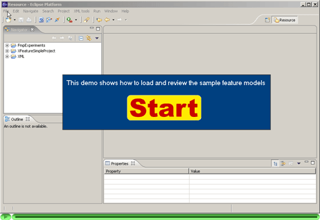
For a quick start you may want to experiment with the two sample models of software
families provided with the standard XFeature delivery. In this case, create a simple
Eclipse project by selecting File | New | Project, then select
Simple and "Project", click "Next" and enter the
project name (e.g. "SampleXFeatureModels"). Download the package of
sample models
and unzip it to the project folder. The two sample feature models shown in the
demo below are IcsrControlSystem.xfm in
ICSR_configuration_files/IcsrControlSystemExample folder and
EShopFMP.xfm in FMP_configuration_files/EShopExample
folder. Click
here
or the thumbnail below to see the demo.
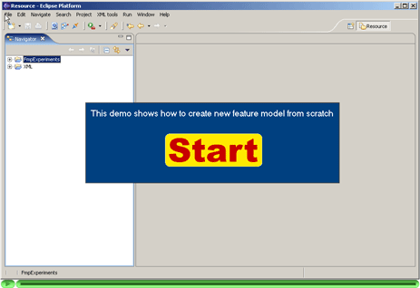
A new feature model is created using a wizard. The wizard is accessible through
menu File | New | Other. Expand item "Other", click
"XFeature Feature Model" and the "Next" button. Follow the
instructions of the wizard on the next two wizard pages. Select the file name and the
location and name of the feature model. Browse your folders to locate the feature
meta-model and display model. If you do not have a feature meta-model and a display
model, consider using one our default
configurations. There is a demo that shows the whole process step by step. Click
here
or the thumbnail below to see the animation.
The XFeature is a configurable tool. The tool configuration, and hence the tool behaviour, is defined by a set of configuration files. Some of these configuration files are intended to be user-defined. Taken together, they define:
Note that the tool is delivered with four sets of default configuration files. These are described elsewhere.
Other configuration files are instead fixed (they might become user-defined in future releases of the XFeature tool) and users should use the default versions of the files that are delivered with the tool.
The table below lists all the configuration files for the XFeature tool. Filenames that contain the string "<name>" designate files that can be modified by the user and that have to be provided by the user (default configuration files serve as examples). Other filenames designate files that are provided with the tool and that are fixed and should not be modified by the users.
| Filename | Description |
|---|---|
| build.xml | Ant build file that runs model verfication and/or application configuration files generation |
| xfbuild.xml | Ant build file that runs model verfication and/or application configuration files generation; this file is automaticaly generated by from a project file <name>.xfp |
| <name>.xfp | project file that contains the tool configuration; it is (together with the generated xfbuild.xml) an alternative to an older build.xml |
| <name>.xdm | display model; XML file that defines how feature model is rendered by the tool |
| <name>.xfmm | feature meta-model; XML file that defines structure of the feature models |
| <name>XdmGen.xsl | application display model generator |
| <name>XfmmGen.xsl | application feature meta-model generator |
| DisplayMetamodel.dmm | XFeature display meta-model that defines the structure of display models |
| DisplayModelCompiler.xsl | XSL program that generates validators of display model completeness |
| DisplayType.xsd | XML Schema file that defines types of visual entities of XFeature tool |
| GlobalConstraintCompiler.xsl | XSL program that generates validators of global constraints |
| GlobalConstraintsMetaModel.xsd | XML Schema file that defines structure of global constraints definition files |
| MetaMetaModel.xfmmm | XFeature meta-meta-model that defines
structure of user-defined <name>.xfmm
files |
| schematron-basic.xsl | reference implementation of Schematron; generates XSL program to validate the feature meta-models |
| skeleton1-5.xsl | reference implementation of Schematron; file is imported to
schematron-basic.xsl
|
| xfmRemoveUniqueNames.xsl | XSL program that simplifies the feature model file before applying the global constraints check |
| XSD2Schtrn.xsl | XSL program that extracts Schematron rules to validate feature meta-models |
The user-defined configuration files should be validated. Valid configuration is guaranteed to work with the XFeature. Since both feature meta-model and feature display model are XML files, the XFeature tool provides XML Schema files that can be used to validate these two user-defined configuration files. Additionally the XFeature tool provides XSL program that checks that display model cover all displayable entities of the feature meta-model. The next table lists the files that should be validated and indicates for each how the validation should be performed:
| Filename | Validation |
|---|---|
| <name>.xdm | Display model has to be validated twice. First, the display model has to
be validated against theDisplayMetamodel.dmm. The
DisplayMetamodel.dmm verifies the structure of
the display model. Second, the display model has to define display
properties for all displayable elements in the feature
meta-model. This is verified in two steps: (a) the
DisplayModelCompiler.xsl program is applied to the
feature meta-model <name>.xfmm and the XSL
program DisplayModelVerifier.xsl is generated. (b) The
DisplayModelVerifier.xsl is applied to the user-defined
display model <name>.xdm. Error is reported
if there is a meta-model element that has no corresponding element in
display model.
|
| <name>.xfmm | The feature meta-model has to be validated twice. First, the feature
meta-model has to be validated against MetaMetaModel.xfmmm.
The MetaMetaModel.xfmmm (XML Schema Definition file)
verifies the structure of the feature meta-model. Second, several
additional restrictions on a valid feature meta-model have to be
checked. These restrictions are expressed as Schematron rules. These rules
are processed in three steps: (a) the Schematron rules are extracted
from MetaMetaModel.xfmmm by applying the XSL program
XSD2Schtrn.xsl to it. (b) The Schematron rules are
compiled to the schematron.validator.xsl XSL program by
applying the schematron-basic.xsl XSL program. (c) The XSL
program schematron.validator.xsl is applied to the feature
meta-model. Error is reported if there is some of the schematron rules
is violated. The whole procedure is discussed in detailhere. |
The next table lists all file extensions that are relevant to the XFeature tool:
| File Extension | Explanation |
|---|---|
| dmm | Display Meta-Model |
| dtd | (W3C) Data Dype Definition |
| pos | POSition file, auxiliary file created by XFeature tool to store the feature model layout |
| sch | SCHematron schema definition (extracted from *.xfmmm) |
| txt | TeXT file |
| xdm | XFeature Display Model |
| xfm | XFeature Model (feature model) |
| xfmm | XFeature Meta-Model (feature meta-model) |
| xfmmm | XFeature Meta-Meta-Model (feature meta-meta-model) |
| xgc | XFeature Global Constraints Definition attached to a feature model |
| xgcc | Global Constraint Checker (XSL file, generated from *.xgc file) |
| xml | Ant build file (build.xml or xfbuild.xml) used to run model validation and application meta-model generation |
| xfp | XFeature project file used to automaticaly generate the Ant build file xfbuild.xml |
| xsd | (W3C) XML Schema Definition |
| xsl | (W3C) eXtensible Stylesheet Language file |
The following demo shows how a feature model can be edited. The FMP configuration is used in this example. Demo shows the following:
MyNewFeatureModel.xfm is opened (it is the same file that has
been created in the previous demo).GroupNode (displayed as green dot) is added. This node is always
attached to its parent. Its cardinality is set to 1..2.GroupNode node are added (both are of type
GroupedFeature). Note the semantics of their parent’s
cardinality (1..2) -- it defines that at least one and at most two
subfeatures make meaningful application. Thus the GroupNode defines
constraint on legal combinations of its children.SolitaryFeature. This one has
no relation with GroupedFeature1 and GroupedFeature2.SolitaryFeature is added and edited.SolitaryFeature is defined to have an attribute of type integer.
This is specified by two dot-shaped nodes – both attached to their parent. Two
properties of the integer attribute are specified.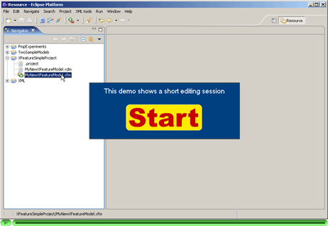
This section describes how to perform the transition from the family level to
application level. The transition process is demonstrated on a simple example of family
of control systems. The FD
configuration is used in this example and files referred to in this section can
be found in src/FD_configuration_files/SimpleControlSystemExample.
First, the family feature model (SimpleControlSystem.xfm) has to be defined
by the user. Structure and visual rendering of the feature model are defined by feature
meta-model FD.xfmm and display model SimpleControlSystem.xdm (a local copy
of FD.xdm). These two files are assigned to the family feature model when
it is being created -- on the first page of the wizard.
Once the family model is defined it is possible to verify that it complies with its
meta-model (in our case FD.xfmm) and generate the application meta-model
and application display model. Both the verification and generation is provided by FD configuration
files. In particular the build.xml file of the FD configuration
provides target generate that manages the verification and generation. This
target accepts five parameters:
The target generate is called from an Ant build file
(build.xml) in the
src/FD_configuration_files/SimpleControlSystemExample
folder. When the default target of this build file is run it creates the
application meta-model (SimpleControlSystemApp.xfmm) and application
display model (SimpleControlSystemApp.xdm).
New application feature model can be created using wizard or existing feature model can
be opened following the instructions at the top of this
page. For an example of existing application feature model see
SimpleControlSystemApp.xfm.
The following demo shows how to perform the above described procedure
within the XFeature tool. Using XFeature tool the user is decoupled from using
build.xml Ant file. Instead he defines the tool configuration using so
called Project Editor. The tool translate the project file to xfbuild.xml Ant
file itself. The user runs the validate and generate tasks by
clicking two dedicated buttons in the toolbar.
The demonstration has 11 steps:
Click
here
or the thumbnail below to see the animation.
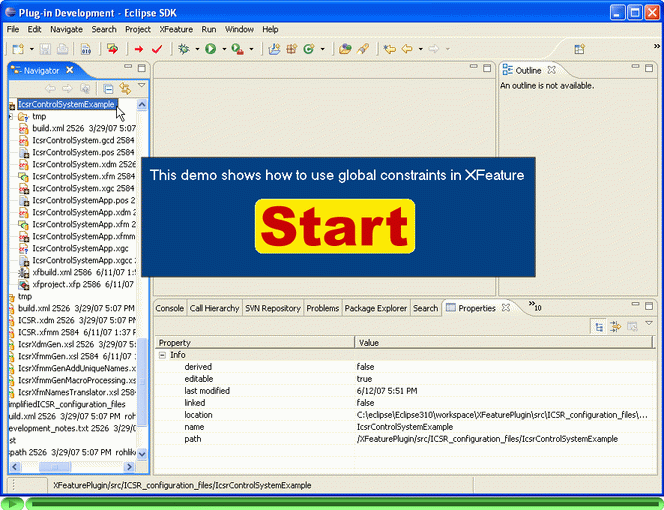
The following demo shows how to define global constraints for a family of control systems
and how the instance of the family is checked agains the global constraints. The feature
model used in this demo is one of the examples
distributed with XFeature. It is located in
src/ICSR_configuration_files/IcsrControlSystemExample.
Note that there as a whole section devoted to global constraints where both rationale, supported types of global constraints, and implementation details are dicussed.
Click
here
or the thumbnail below to see the animation.